Farras Palevi Ariyawan-Department of Mechanical Engineering, Universitas Indonesia
Abstract
This study presents a comprehensive computational fluid dynamics (CFD) analysis of flow characteristics in a circular channel with and without fin modifications, with particular emphasis on pressure drop, mesh independence, friction factor, secondary flow behavior, and pumping power requirements. A systematic mesh refinement study was conducted to ensure numerical accuracy and solution independence. The results indicate that the pressure drop for the no-fin configuration converges smoothly as mesh density increases, whereas the finned configuration exhibits slightly higher sensitivity due to increased geometric complexity. The final converged pressure drops are approximately 3.40 kPa for the no-fin case and 12.86 kPa for the finned case, demonstrating a substantial increase in flow resistance caused by the presence of fins. Further analysis reveals that the finned geometry produces a significantly higher friction factor (0.371) compared to the no-fin configuration (0.1), indicating enhanced viscous dissipation and flow obstruction. This directly impacts the pumping power requirement, where the finned system demands approximately 34.61 W, nearly four times higher than the 9.19 W required for the smooth channel. Visualization of the velocity field highlights the development of stronger secondary flow structures in the finned case, attributed to flow separation and recirculation induced by geometric disturbances. Overall, the study demonstrates that while fins can alter flow structures and potentially enhance mixing, they impose a considerable penalty in terms of pressure drop and energy consumption.
1. Introduction
Waste management and energy demand have become increasingly pressing global issues. Waste streams including biomass, plastics, rubber, and agricultural residues continue to rise, posing serious environmental threats if not managed effectively. Concurrently, the depletion of fossil fuels and the urgency to meet greenhouse gas emission reduction targets have driven the development of sustainable alternative energy technologies. One such technology gaining significant attention is pyrolysis. Pyrolysis is a thermochemical conversion method used to transform waste into value-added products such as biochar, bio-oil, and syngas. Animal manure biomass represents a high-potential feedstock due to its abundance, yet it remains underutilized. However, the efficiency of the pyrolysis process is not only influenced by thermal behavior but also by flow characteristics within the reactor, particularly pressure drop, which directly affects energy consumption and operational performance [1]. For instance, biochar produced at 600 °C exhibits high resistance to aging and superior carbon structural stability [2]. Consequently, understanding flow resistance and pressure distribution within the reactor is critical.
Various reactor types and heating configurations are employed in animal manure pyrolysis, including the fixed-bed reactor combined with a helical heating element [3]. Helical heating elements not only enhance heat transfer performance but also significantly influence flow behavior, with Nusselt numbers typically increasing by 8–12% [4]. This enhancement is closely associated with the formation of secondary flows known as Dean vortices. This phenomenon arises from centrifugal forces as the fluid traverses a circular path, creating two counter-rotating circulation vortices within the pipe cross-section [8]. These secondary flow patterns improve mixing but simultaneously increase flow resistance, contributing to higher pressure drop along the system. Helical elements are frequently utilized in heat exchangers as external components for heat absorption and dissipation [4][5][6][7]. Recent structural innovations to improve efficiency include the integration of loops [7] and the addition of fins within the helical piping [6]. Furthermore, research indicates that larger helical coil diameters can suppress secondary flows, thereby reducing both mixing intensity and pressure drop [7].
Numerous studies have utilized Computational Fluid Dynamics (CFD) to analyze flow characteristics within pyrolysis reactors. This approach enables the visualization of velocity fields, vortex structures, and pressure distribution, as well as the identification of regions with high flow resistance. Advanced models have also integrated reaction kinetics (reaction-coupled models) to simulate biomass decomposition under realistic conditions. Despite extensive research on reactor performance, there remains a gap in studies specifically evaluating the influence of external helical heating configurations on pressure drop behavior. Most existing literature relies on simplified heating models, such as constant heat sources or internal heating, which may not accurately represent the actual conditions of external heating systems. Therefore, this study focuses on the application of a helical heating element positioned on the exterior of the reactor, diverging from conventional internal configurations. The effectiveness of this external helical heater is evaluated based on the addition of fins with emphasis on flow resistance and pressure drop characteristics.
2. Methodology
This study employs Computational Fluid Dynamics (CFD) to numerically investigate and compare the flow characteristics of two distinct helical coil configurations: a conventional helical coil and a modified helical coil integrated with internal fins, applied as external heating elements for a pyrolysis reactor. By implementing a mesh-independent grid and appropriate turbulence models, the simulation captures the development of secondary flow structures, including Dean vortices, within both configurations. The comparative analysis focuses on how the internal fin geometry alters fluid dynamics, particularly in terms of flow resistance and pressure drop relative to the standard configuration.
The impact of these two configurations is evaluated based on pressure distribution, flow uniformity, and overall frictional losses along the helical coil. The CFD model analyzes how the presence of internal fins modifies vortex intensity and enhances mixing while potentially increasing pressure drop. Furthermore, the simulation results are used to quantify the trade-off between improved flow behavior and the additional energy required for fluid transport, providing insight into the efficiency of each configuration from a hydrodynamic perspective.
2.1. Geometric Modeling
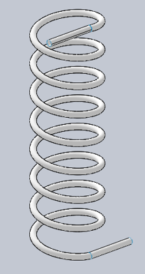
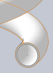
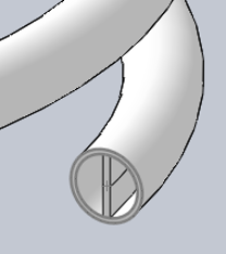
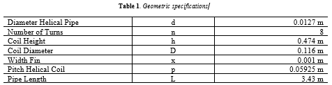
2.2. Numerical Methodology
2.2.1. Curvature Ratio & Dean Number
Curvature ratio and Dean number (De) are the fundamental non-dimensional parameters governing fluid flow in helical configurations. The curvature ratio, defined as
quantifies the geometric severity of the bend. The Dean number incorporates this geometric effect into the inertial-to-viscous force balance, formulated as
It characterizes the magnitude of the centrifugal forces that induce secondary flow patterns within the cross-section.
2.2.1. Governing Equations
The continuity equation represents the principle of mass conservation in fluid flow. For incompressible flow, it states that the divergence of the velocity field is zero, meaning that mass is neither created nor destroyed within the control volume. This equation ensures that the inflow and outflow mass rates remain balanced.
The energy equation was not considered in the present study as the primary objective is to investigate the hydrodynamic behavior of the flow within the helical coil, rather than the thermal characteristics. The analysis is focused on velocity distribution, pressure field, and flow structures, which can be sufficiently described using the continuity and momentum equations alone.
2.2.1. Pressure Drop Calculation
The pressure drop across the helical coil is defined as the difference between the inlet and outlet static pressures. This approach is commonly employed in CFD simulations, where pressure values are directly obtained from the solution field.
2.2.1. Friction Factor Calculation
The friction factor was determined to quantify flow resistance, while the required pumping power was calculated to evaluate the energy consumption of the system. Both parameters were obtained using the formulations and correlations presented in [6].
Thus the required pumping power:
Where A is cross-sectional area of pipe.
2.3. Boundary Conditions & Fluid Properties
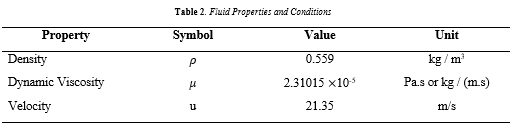
The boundary conditions applied in this CFD study are defined to represent the physical behavior of exhaust gas flow from an internal combustion engine (ICE) fueled by LPG within a helical coil system. Each condition plays a specific role in ensuring numerical stability and physical realism of the simulation.
- Inlet : A velocity inlet boundary condition with a constant magnitude of is imposed at the inlet. This specification assumes that the exhaust gas enters the domain with a uniform and steady velocity profile.
- Outlet : The outlet is defined using an outflow boundary condition, which assumes that the flow is fully developed at the exit and that no information propagates upstream into the computational domain.
- Wall : All walls of the helical coil are treated as stationary walls with a no-slip condition. This implies that the fluid velocity at the wall surface is zero
2.4. Simulation Model
The present study assumes an incompressible, steady-state flow modeled using Large Eddy Simulation (LES) to balance physical accuracy and computational efficiency. The incompressible assumption is valid due to the relatively low flow velocity (21.35 m/s), corresponding to a low Mach number, where density variations can be neglected. The steady-state approach is employed to capture the overall flow characteristics, such as pressure drop and curvature-induced secondary flows, without considering temporal fluctuations. Meanwhile, LES is utilized to resolve large-scale turbulent structures, particularly Dean vortices generated by the helical geometry, while modeling smaller scales, thereby providing a more accurate representation of complex turbulent flow compared to conventional RANS models.
2.5. Y+ Calculation
The dimensionless wall parameter represents the normalized distance of the first computational cell from the wall and is defined as:
where is the distance of the first cell center from the wall, is the friction velocity, is the fluid density, and is the dynamic viscosity.
Based on the provided results, a target value of is selected, which places the first mesh layer within the viscous sublayer of the boundary layer. This is a critical region very close to the wall where viscous effects dominate and velocity gradients are steep. To satisfy this requirement, the estimated first cell height (wall distance) is calculated as:
2.6 x 10^-5 m
This very small value indicates that the mesh near the wall is sufficiently refined to directly resolve the viscous sublayer without relying on wall functions.
The choice of is particularly important when using Large Eddy Simulation (LES), as LES requires fine near-wall resolution to accurately capture the interaction between turbulence structures and the wall [14]. Unlike RANS models that can use wall functions at higher values (e.g., ), LES benefits from resolving the near-wall flow directly to improve prediction accuracy of shear stress, velocity profile, and pressure drop.
In summary, the obtained result confirms that the mesh design is appropriate for high-fidelity simulation, ensuring that near-wall physics are well-resolved and consistent with the requirements of LES modeling.
3. Results and Discussion
3.1. Mesh Independency Study
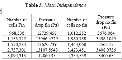
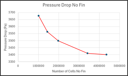
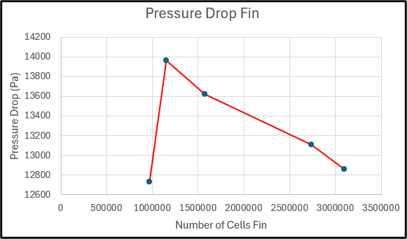
Table 3 presents the results of the mesh independence study for both configurations, namely the case with fins and without fins, evaluated in terms of pressure drop as a function of the total number of computational cells.
A general trend can be observed in both configurations, where increasing the number of cells leads to a gradual stabilization of the predicted pressure drop values. For the no-fin case, the pressure drop decreases consistently from 3988.10 Pa at approximately 0.98 million cells to 3400.65 Pa at around 4.35 million cells. The rate of change becomes progressively smaller at higher mesh densities, with a difference of approximately 0.2% between the last two mesh levels. This behavior indicates that the numerical solution is approaching mesh-independent conditions for the no-fin configuration.
In contrast, the finned case exhibits a less monotonic trend. The pressure drop initially increases significantly from 12,729.46 Pa to 13,966.47 Pa as the mesh is refined, followed by a gradual decrease to 12,860.35 Pa at the highest mesh resolution. Although the variation between the two finest meshes is relatively small (approximately 2%), the earlier fluctuations suggest that the solution is more sensitive to mesh refinement. This behavior is expected due to the increased geometric complexity introduced by the fins, which leads to stronger gradients, flow separation, and local vortical structures that require finer mesh resolution to be accurately captured.
3.2. Pressure Drop Analysis
The pressure drop results obtained from the mesh-independent simulations reveal a significant difference between the finned and non-finned configurations. Under identical operating conditions, the pressure drop in the finned case reaches approximately 12.8 kPa, whereas the non-finned configuration exhibits a substantially lower value of about 3.4 kPa. This corresponds to nearly a fourfold increase in pressure loss due to the presence of fins.
This pronounced increase in pressure drop can be directly attributed to the alteration of the flow field caused by the fins. In the non-finned configuration, the flow develops relatively smoothly along the channel, with minimal obstruction and limited disturbance to the boundary layer. As a result, the dominant source of pressure loss arises from viscous effects, leading to a comparatively low pressure drop.
In contrast, the introduction of fins significantly modifies the flow structure. The fins act as physical barriers that interrupt the flow, forcing the fluid to repeatedly accelerate and decelerate as it navigates around the geometric features. This process induces strong adverse pressure gradients, which promote flow separation and the formation of recirculation zones downstream of the fins. Additionally, the increased surface area enhances wall shear stress, further contributing to viscous dissipation.
This result highlights a critical trade-off. While fins are typically introduced to enhance heat transfer performance. They impose a significant penalty in terms of pressure drop. The nearly fourfold increase in pressure loss implies that higher pumping power would be required to maintain the same flow rate, which may reduce the overall system efficiency.
3.2. Friction Factor Analysis
The friction factor and pumping power were evaluated by equation (6) and (7) to assess the hydraulic performance of both finned and non-finned configurations. The results indicate that the finned configuration exhibits a significantly higher friction factor of 0.371 compared to 0.1 for the non-finned case. This substantial increase reflects the enhanced flow resistance induced by the presence of fins, which disturb the flow and promote additional momentum loss.
In terms of energy requirement, the minimum pumping power for the finned configuration was calculated to be 34.61 W, whereas the non-finned configuration required only 9.19 W. This indicates that the introduction of fins leads to a considerable increase in energy consumption, approximately 3.7 times higher than the baseline case without fins.
The higher friction factor in the finned geometry is directly associated with increased pressure losses due to flow separation, vortex formation, and surface interaction. Consequently, a greater pressure gradient is required to maintain the same flow rate, resulting in a higher pumping power demand.
3.2. Flow Analysis
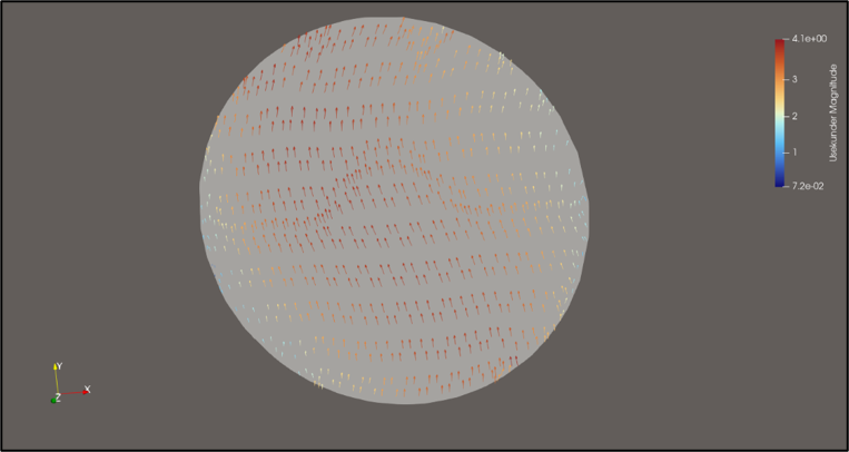
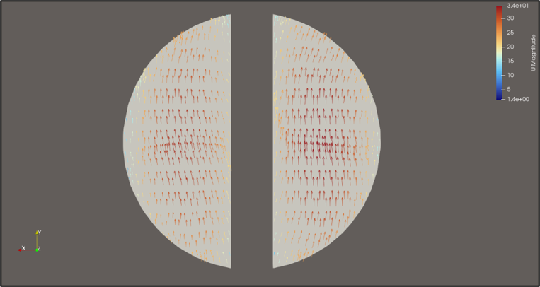
The secondary flow behavior was analyzed for both configurations, namely the no-fin case and the finned case , to evaluate the influence of geometric modification on flow structure. The results reveal a significant transformation in the flow pattern due to the presence of fins.
In the no-fin configuration , the velocity vectors are predominantly aligned with the main flow direction, indicating a relatively uniform and stable flow field. Only minor deviations are observed near the wall region, which are primarily associated with boundary layer development. The absence of internal obstructions results in weak secondary flow, with limited transverse motion and minimal momentum exchange in directions perpendicular to the primary flow. In contrast, the finned configuration exhibits a markedly different flow structure. The introduction of fins disrupts the flow, generating strong secondary motion characterized by significant deviations in velocity direction. This behavior is caused by flow separation, reattachment, and the formation of localized vortices around the fin surfaces. As a result, the flow becomes highly three-dimensional, with enhanced mixing and increased interaction between fluid layers.
4. Conclusion
A detailed CFD investigation has been conducted to evaluate the influence of fin structures on flow behavior, pressure drop, and energy requirements within a circular channel. The mesh independence study confirms that the numerical results are reliable, with minimal variation observed at higher mesh resolutions, thereby validating the computational approach. The presence of fins significantly increases the pressure drop compared to the smooth (no-fin) configuration. Objectively, the pressure drop rises from approximately 3.40 kPa in the no-fin case to about 12.8 kPa in the finned configuration. This substantial increase is consistent with the higher friction factor obtained for the finned geometry, indicating stronger flow resistance and enhanced momentum loss. In addition, the pumping power analysis demonstrates that the finned configuration requires considerably more energy to maintain the same flow conditions. The calculated minimum pumping power increases from 9.19 W (no-fin) to 34.61 W (fin), highlighting a clear trade-off between flow modification and energy efficiency. The analysis of secondary flow patterns further supports these findings, showing that the finned geometry induces more complex flow structures, including recirculation zones and non-uniform velocity distributions. While these features may be beneficial for applications requiring enhanced mixing or heat transfer, they also contribute to increased hydraulic losses. In summary, the study concludes that the incorporation of fins leads to improved flow disturbance and secondary motion at the expense of significantly higher pressure drop and pumping power. Therefore, the use of fins must be carefully evaluated based on the intended application, particularly when balancing performance enhancement against energy efficiency considerations.
5. References
[1] Ibrahim, S., Chen, W. H., Chong, C. T., & Ok, Y. S. (2022). Valorization of animal manure via pyrolysis for bioenergy: A review. Journal of Cleaner Production, 343, 130965
[2] Cárdenas-Aguiar, E., Méndez, A., Paz-Ferreiro, J., Sohi, S. P., & Gascó, G. (2023). Thermal analysis of aged chars obtained by pyrolysis and hydrothermal carbonisation of manure wastes. Journal of Thermal Analysis and Calorimetry, 148(14), 7395–7401. https://doi.org/10.1007/s10973-023-12199-w
[3] Illa Rizianiza et al. (2025). J. Phys.: Conf. Ser. 2972 012001
[4] Flayyih, R. A., Alwan, K. J., & Aljaberi, H. A. (2025). Comparative heat transfer analysis of helical coil and straight tube heat exchangers. Case Studies in Thermal Engineering, 76, 107386. https://doi.org/10.1016/j.csite.2025.107386
[5] Chater, H., Asbik, M., Mouaky, A., Koukouch, A., Belandria, V., & Sarh, B. (2023). Experimental and CFD investigation of a helical coil heat exchanger coupled with a parabolic trough solar collector for heating a batch reactor: An exergy approach. Renewable Energy, 202, 1507–1519.
[6] Alklaibi, A. M., & Tlili, I. (2026). Toward compact helical heat exchanger with fins-based design. International Communications in Heat and Mass Transfer, 172, 110425.
[7] Yekani, S. K., Golmarz, T. P., Ranjbar, S. F., & Borousan, S. (2026). Data-driven geometric optimization of helical tube heat exchangers for enhanced heat transfer with acceptable pressure drop. International Journal of Thermofluids, 32, 101565.
[8] Ma, C., Gu, Y., Cheng, J., Sun, H., & Cheng, L. (2026). Analysis of Dean vortices and sediment distribution in inlet passage of nearshore pump stations under solid-liquid two-phase conditions. Applied Ocean Research, 170, 105043.
[9] Kurniawan, A., Sugiarto, B., & Perdana, A. (2020). Design of a simple pyrolysis reactor for plastic waste conversion into liquid fuel using biomass as heating source. Eksergi, 17(1).
[10] Yu, S., Zhang, H., Liu, Z., Yi, T., Mao, X., Liang, X., & Nie, Y. (2025). Design and optimization of electromagnetic induction heating pyrolysis reactor based on load impedance model and heat transfer model. Chemical Engineering Journal, 509, 160851.
[11] Ahmad Indra Siswantara et al. (2025). J. Phys.: Conf. Ser. 2972 012016
[12] Saleh, S. A., Kadhim, Z. K., & Khalaf, K. A. (2023). CFD simulation of helical coil heat exchanger with different coil pitch to heating heavy fuel oil. Wasit Journal of Engineering Sciences, 11(3), Artikel 472. https://doi.org/10.31185/ejuow.Vol11.Iss3.472
[13] Che S, Breitenmoser D, Infimovskiy YY, Manera A and Petrov V. (2020). CFD Simulation of Two-Phase Flows in Helical Coils. Front. Energy Res. 8:65. doi: 10.3389/fenrg.2020.00065
[14]Duan, Z., & Wang, Z. J. (2024). Calibrating sub-grid scale models for high-order wall-modeled large eddy simulation. Advances in Aerodynamics, 6(5).
[15] Chunxue Zhang et al 2025 J. Phys.: Conf. Ser. 3092 012011
[16] Teng Pan, Yue Qu, Yuelin Yang, Zhen Tian, Youwei Cheng, Lijun Wang, Xi Li. (2022). Numerical study of gas-phase pyrolysis reaction with turbulent flow in helically coiled tubes,. Chemical Engineering and Processing – Process Intensification,Volume 170,108660,ISSN 0255-2701. https://doi.org/10.1016/j.cep.2021.108660.
[17] Hou, Y., Sun, H., Li, J., Zhang, C., Gao, C., Chen, B., & Li, W. (2024). Numerical study of heat transfer and pressure drop characteristics in helical tubes based on OpenFOAM. Annals of Nuclear Energy. https://doi.org/10.1016/j.anucene.2024.110889
[18] Onal, B., Kirkar, S. M., Akgul, D., Celen, A., Acikgoz, O., Dalkılıç, A. S., Kazi, S., & Wongwises, S. (2021). Heat Transfer and pressure drop characteristics of two-phase flow in helical coils. Thermal Science and Engineering Progress. https://doi.org/10.1016/j.tsep.2021.101143
[19] Kumar, E., Solanki, A., & Kumar, M. (2021). Numerical investigation of heat transfer and pressure drop characteristics in the micro-fin helically coiled tubes. Applied Thermal Engineering, 182, 116093.https://doi.org/10.1016/j.applthermaleng.2020.116093
[20] Zheng X, Lu X, Gao Y, Jin D, Hu Y, Hu Y and Mao Y (2023), Experimental study on friction pressure drop and circumferential heat transfer characteristics in helical tubes. Front. Energy Res. 11:1204850. doi: 10.3389/fenrg.2023.1204850
[21] Prakash, A., & Chandraker, D. (2025). Numerical & experimental study of single-phase flow in helically coiled pipes for laminar & turbulent regimes. Progress in NuclearEnergy.https://doi.org/10.1016/j.pnucene.2025.105637