1. The Relationship Between Numerical Methods and Finite Element Method (FEM) Simulation
Numerical methods are a branch of applied mathematics focused on solving mathematical problems using computational approaches. In engineering and science, we often encounter complex problems that cannot be solved analytically (i.e., with exact formulas). This is where numerical methods play a critical role, as they allow us to obtain approximate but sufficiently accurate solutions for problems such as force analysis, stress, displacement, fluid flow, and thermal changes in engineering systems. One of the most influential numerical methods in mechanical, civil, and electrical engineering is the Finite Element Method (FEM). FEM is used to solve partial differential equations (PDEs) that describe physical phenomena by breaking down complex structures into smaller interconnected elements.
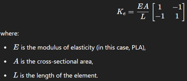
In principle, FEM approximates the solution function of a continuous system by converting it into a discrete system that can be computed using a computer. Each element has a shape function and a local stiffness matrix, which are then assembled into a global matrix—a process known as discretization. In the context of my previous project, numerical methods were applied using FreeCAD to calculate displacement and von Mises stress in a PLA-generic bracket subjected to a downward force of 50 N. This was done by dividing the bracket into small triangular or tetrahedral elements through meshing, followed by constructing a system of equations based on structural mechanics principles, especially Hooke’s Law and force equilibrium. Mathematically, FEM formulates a linear system in the form:
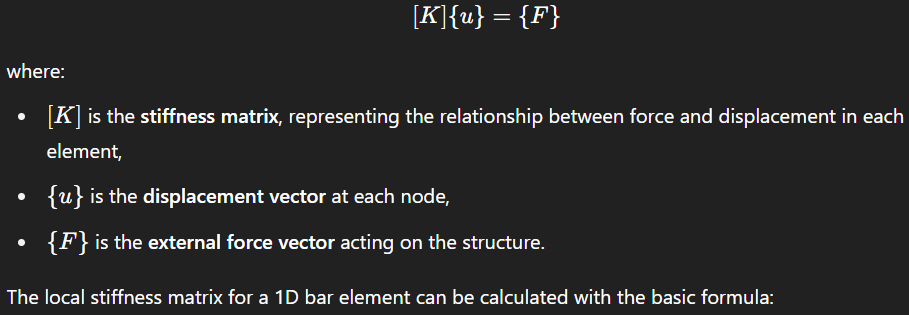
In the simulation, values such as E and other material properties are explicitly input into the software, which then assembles all these elements into a global matrix. Once the system [K]{u}={F} is constructed, it can be solved using various numerical techniques, such as Gaussian elimination, LU Decomposition, or iterative methods like Gauss-Seidel, particularly for large systems.
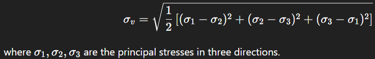
The simulation results, such as von Mises stress and maximum displacement, are numerical outputs derived from this solution process. The von Mises stress is calculated based on principal stresses and serves as an indicator of whether a component may yield (fail), especially for ductile materials. The 3D von Mises formula is:
Overall, this entire simulation process is fundamentally rooted in numerical methods, from discretization, formulating the linear system, to solving it, all relying on numerical computation algorithms. Therefore, by understanding numerical method theory, I am better able to comprehend the logical and technical workings of FEM simulation, not just as a software operation. This proves that numerical methods are not merely abstract mathematical concepts but serve as a vital foundation for solving modern engineering problems.
2. Simulation
I. Deep Awareness of I
I started this analysis process by realizing that I am still learning, and every step I take is part of my development process as a future engineer. I realized that my bracket design was not just a 3D drawing, but could represent how responsible a designer is in ensuring a product is safe and functions properly. While deciding on the size, material, and style given to the model, I also realized that these choices were highly dependent on my current understanding. Therefore, I tried to be careful with every decision, from choosing PLA as the material, to how the 50N force was applied to one side of the bracket. I wanted to make this process not only a duty obligation, but also an exercise in critical thinking and technical responsibility. Also, I kept trying to maintain the awareness that this design, if implemented in the real world, should be safe and reliable.
II. Intention
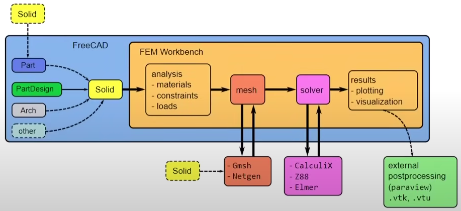
In working on this simulation, my main intention was to learn and understand how mechanical designs can be tested virtually before they are actually built. I wanted to ensure that every decision I made, from material selection to loading, had a clear purpose: to make the bracket design safe and efficient when applied in the real world. For this reason, I chose to use FreeCAD as an open-source software that is quite comprehensive for structural modeling and analysis needs. With the help of the FEM Workbench feature in FreeCAD, I was able to apply forces, define boundary conditions, and run simulations with built-in solvers such as CalculiX. In addition to learning about simulation techniques, I also wanted to ensure that the results I obtained could be useful in reflecting the quality and durability of the design, and could be applied in the context of long-term use, such as for the use of brackets in shelving or household appliances. I tried to make the results of this analysis not only technically correct, but also valuable in terms of practicality and sustainability.
III. Initial Thinking
To understand the problem to be analyzed, I first identified the bracket component as an object subjected to a compressive force of 50N on one of the plates, while the other side was anchored to the wall surface. I thought of the various parties that might be affected: the bracket user, the product designer, and even the environment. I placed the problem in a real context, such as in 3D printing applications using PLA for households or light industry. I also explore the underlying causes of potential bracket failures, such as excessive stress in areas of sharp corners or insufficient thickness. In this case, I made sure that any assumptions used, such as material strength and force direction, matched the actual context of use. I used data from the referenced videos to support the analysis, including load values, dimensions, and PLA material properties to make the simulation more accurate.
IV. Idealization
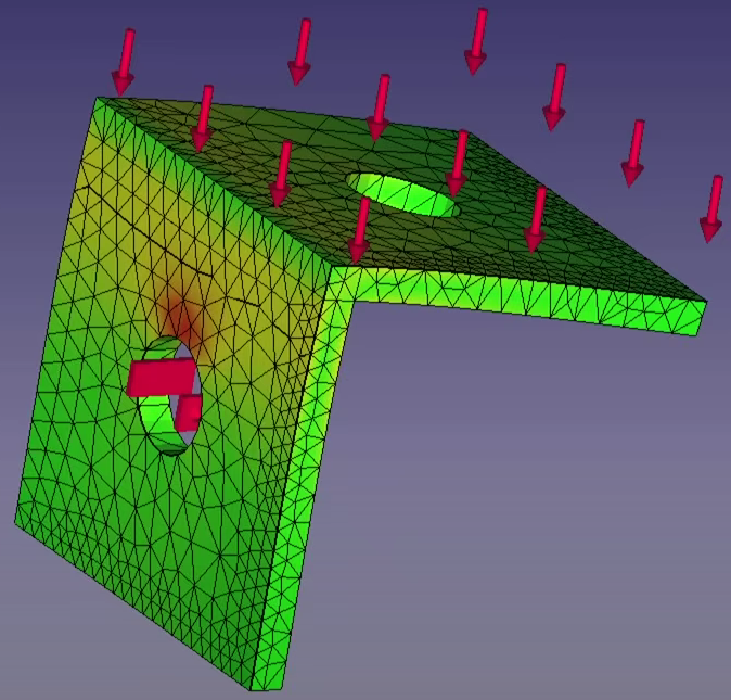
To simplify the problem, I made assumptions such as: the bracket is static, the force acts perpendicular to the surface, and PLA is isotropic although in reality it can be anisotropic depending on the mold direction. I also tried to propose realistic solutions while leaving room for creativity, such as trying simulations under other load conditions when necessary. However, I ensured that the entire approach remained within the laws of physics and principles of material mechanics. I kept the simulation consistent with the original intention: understanding stress and deformation, not just looking for numbers. I also considered that the simulation results could be used for similar cases with different geometries, as the bracket design is modular and generalized. The analysis results also showed the efficiency of the design, not overusing materials, but still being able to withstand the force with a maximum deformation of 3.53 mm and von Mises stress reaching 63.81 MPa, which is still within the strength threshold of PLA.
V. Instruction-Set
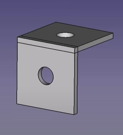
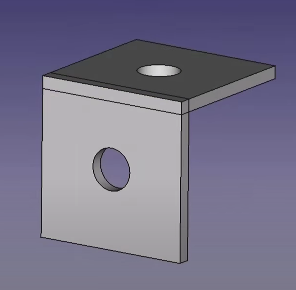
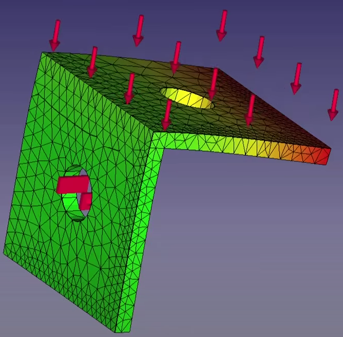
The steps I took in this simulation started with modeling the bracket in FreeCAD, specifically in the Part Design workbench. The bracket has the basic shape of two 1-inch x 1-inch square plates connected perpendicularly on one side. Each plate was given a 0.266-inch diameter hole for bolt placement, and the thickness of the entire plate was set at 0.08 inches. This model was then used as the basis for structural analysis.
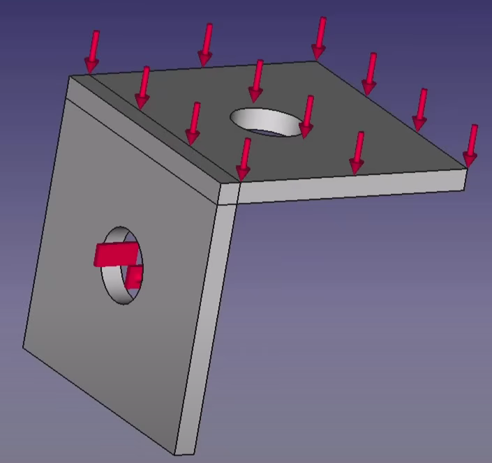
After the design was completed, I proceeded to input the material properties. I used PLA-generic, corresponding to a common material in the 3D printing process, with the aim of simulating the realistic conditions of the printed part. Then, I set the boundary conditions: The vertical plate part was considered to be fixed to the wall using bolts, while the horizontal plate part was loaded with a force of 50 Newtons in the downward direction to represent the actual working load.
The meshing process is performed using a maximum mesh size setting of 5 mm with moderate fineness to obtain a balance between accuracy and computational efficiency. The resultant mesh is dense enough to allow the detection of deformation or stress concentration with sufficient accuracy.
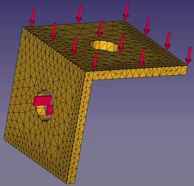
The simulation was then run using the CalculiX solver, which is directly integrated in FreeCAD. From the simulation results, I found that the maximum displacement was 3.53 mm, while the minimum displacement was 0 mm. For the Von Mises stress analysis, the minimum value was 11.19 kPa, and the maximum reached 63.81 MPa, which is the main indication of the vulnerable points that could potentially fail if the load is too high.The meshing process was carried out using a maximum mesh size setting of 5 mm with a moderate level of fineness to get a balance between accuracy and computational efficiency. The resultant mesh is dense enough to allow the detection of deformation or stress concentration with sufficient accuracy.
All of these results were well documented to ensure that they could be reinterpreted if needed. Each step is explained logically and sequentially so that it can be replicated by others. The process also considers sustainability, using common simulation materials and load settings that represent real, not extreme, conditions. The entire analysis is presented in easy-to-understand language, both through narration and visualization of results, while consistently following the working principles of the DAI5 framework.