Pyrolysis Reactor
In this assignment, i designed a 3D Model of a pyrolysis reactor with a constraint dimension of around 1m x 1m x 1m. This pyrolysis reactor is intended to be used for wastes from DAIS cultivation. The heat comes from the exhaust of a generator.
3D Model Design
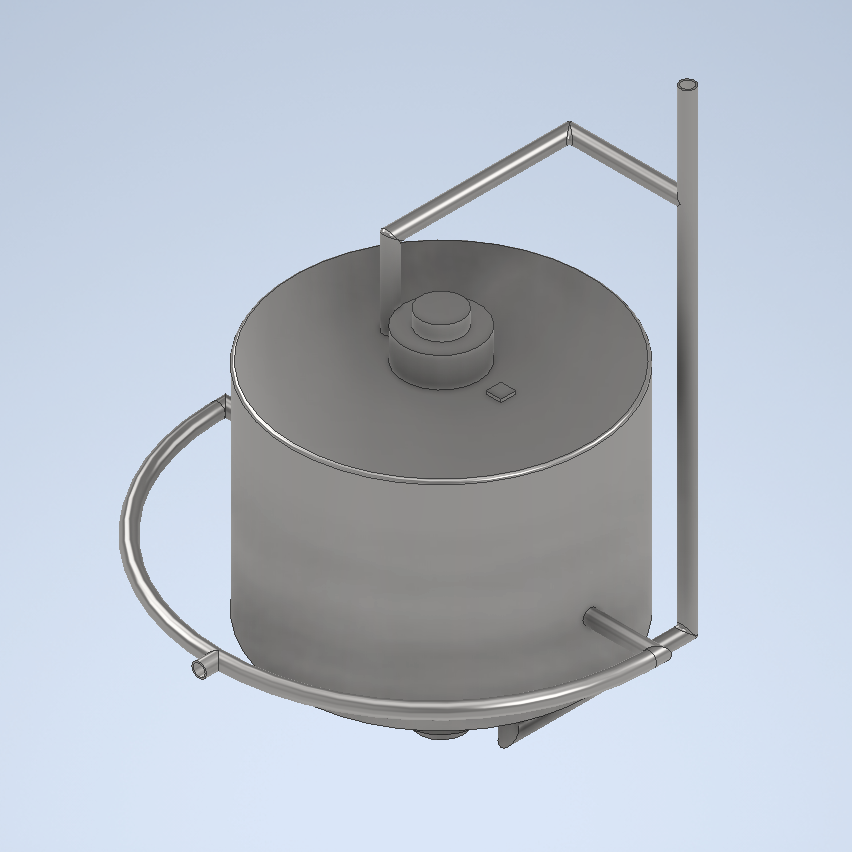
This is the 3D Model that i designed with Autodesk Inventor 2025, i utilized two hot air inlet (from the generator’s exhaust) as seen on the arched piping on the horizontal sides of the reactor. The exhaust air then transferred to the cold outlet pipe as seen on the two straight pipe on the vertical sides.
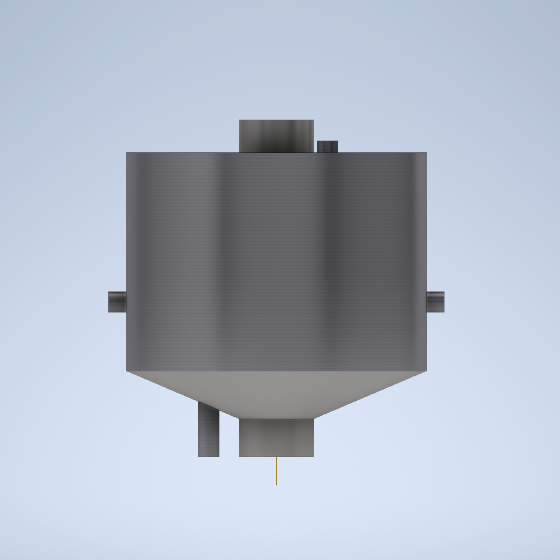
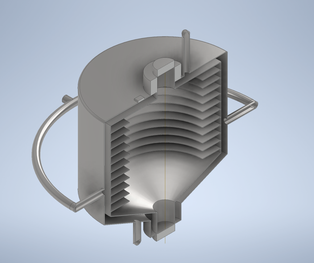
To make the simulation more time efficient in rendering the simulation & analysis, simplifying the reactor design would be best.
Simulation Setup
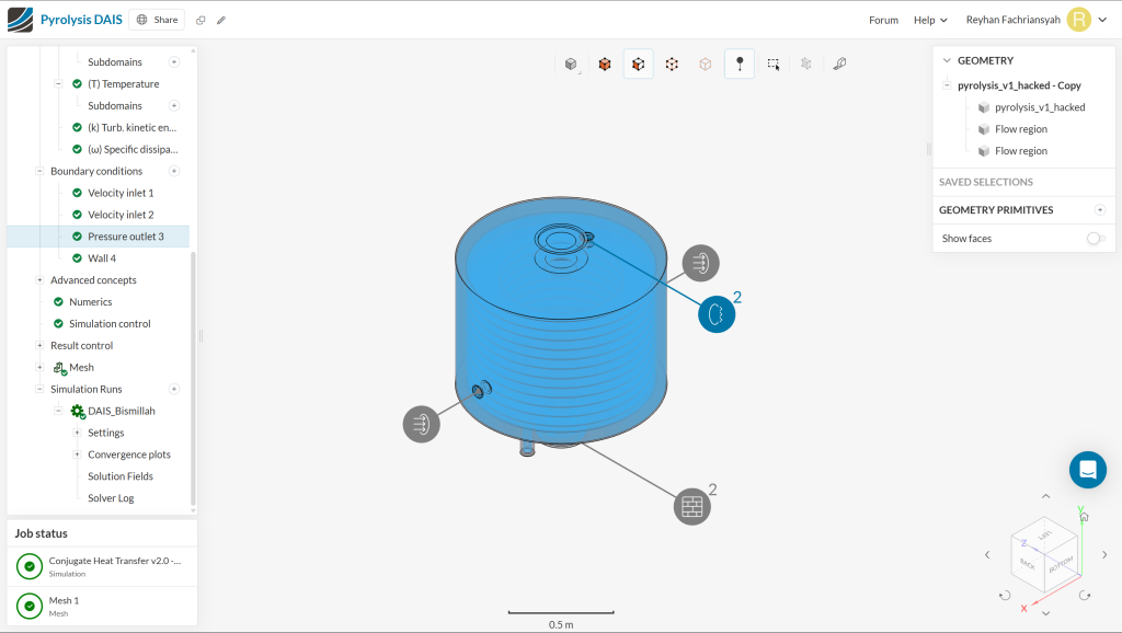
Simulation Type: Conjugate Heat Transfer V2
Solid Material: Steel
Air Inlet Velocity: 8 m/s
Air Inlet Temperature: 500°C or 773.2°K
Gravity (g): 9.8 m/s²
End Time: 300s
Delta t (Time Step Size): 0.1s
Write Control: Time Step
Write Interval: 50
Number of Processors: Automatic (max 16)
Results
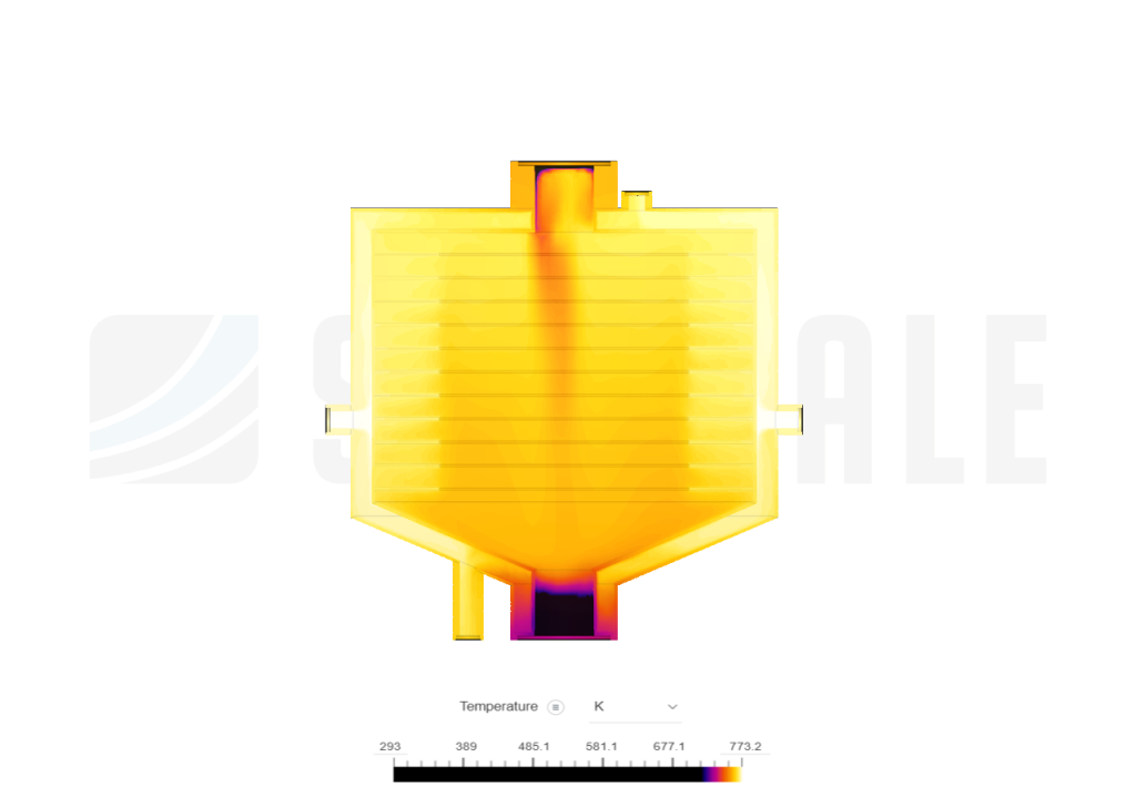
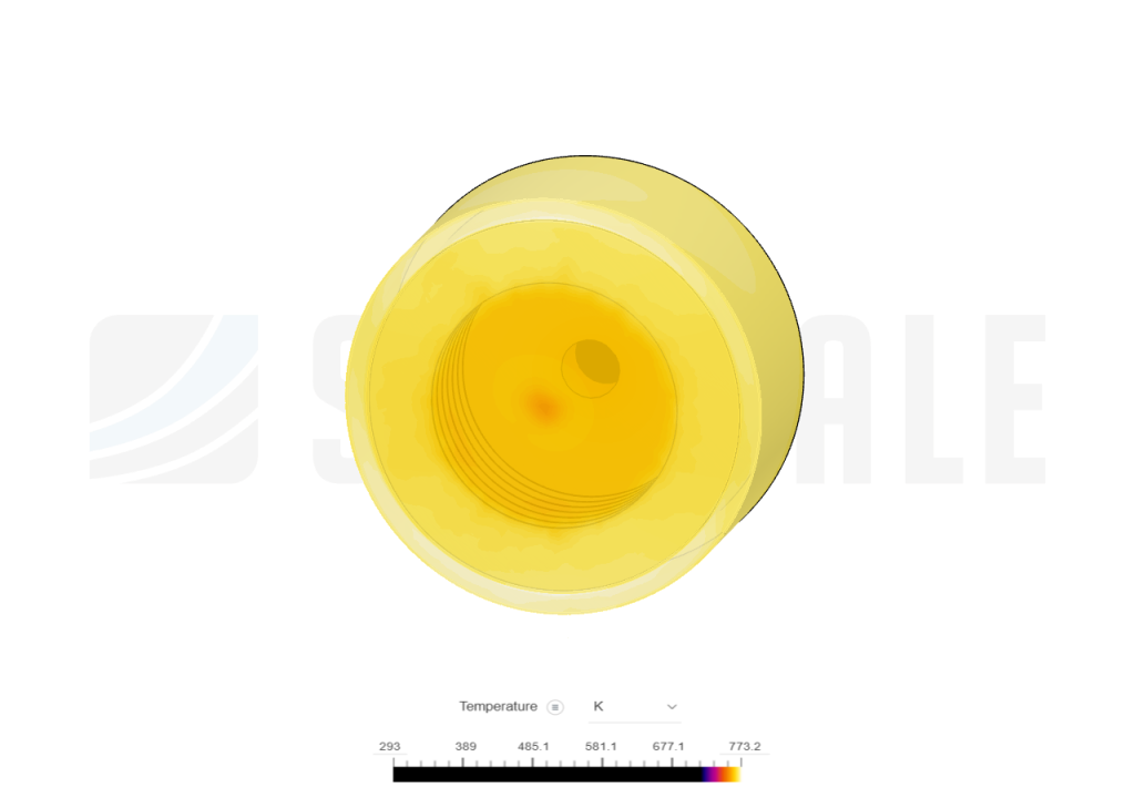
Inner-side of the reactor
Inner-side of the reactor in x-plane
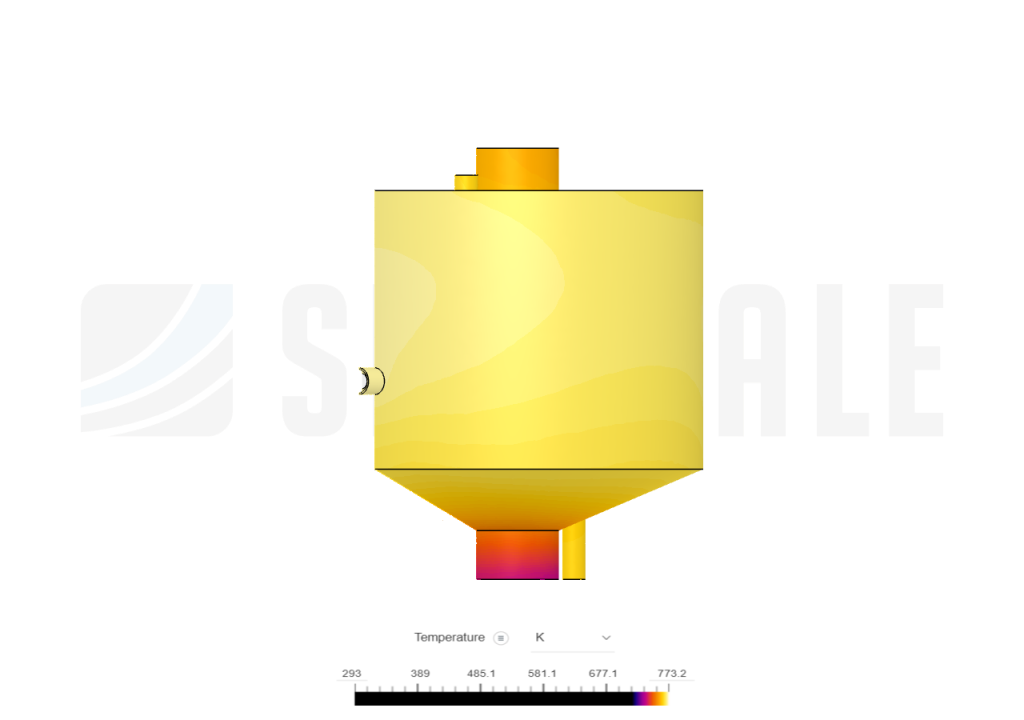
outer-side of the reactor
The simulations mentioned above used Kelvin (K), it is the SI unit of thermodynamic temperature, used to measure temperature in scientific contexts, particularly in physics and chemistry
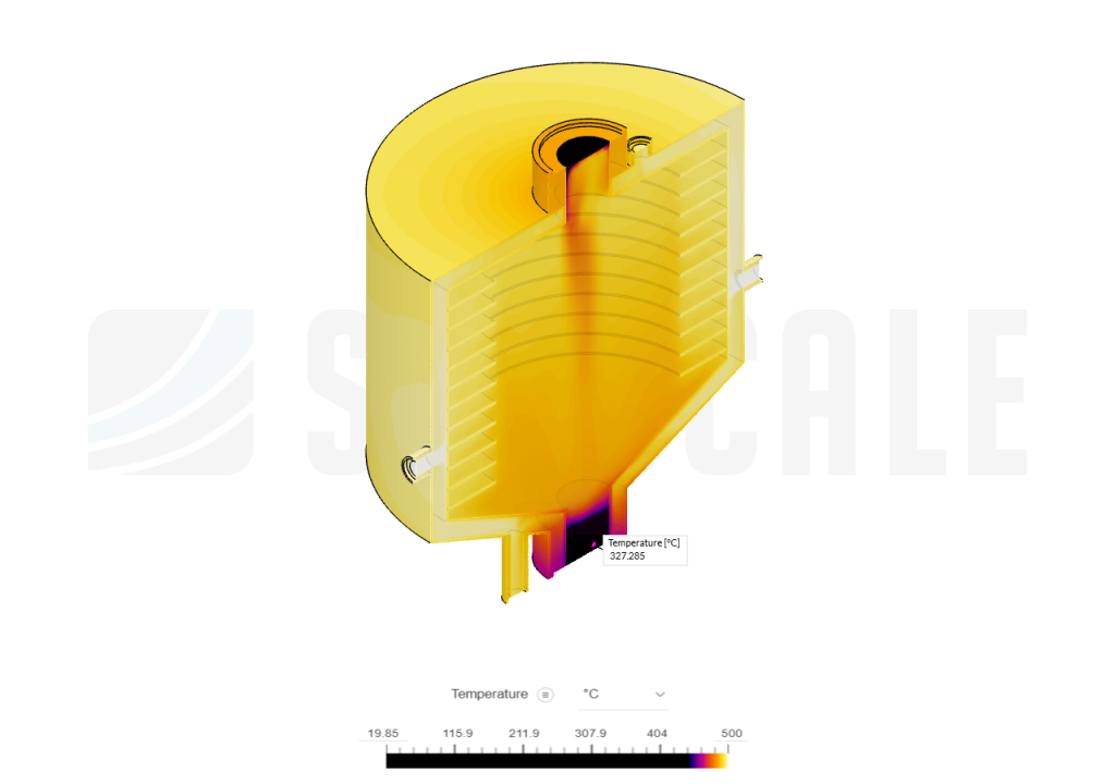
Thermal Analysis Based On The Post-Processing Simulation
For more data variety, i used °C instead of °K for the Legend on this part, since Indonesian used to using Celcius more than Kelvin.
Based on the the inspect pointer pointed on the lowest-temperature region of the pyrolysis reactor which is 327.2 °C is sufficient for the pyrolysis process while it is important to mention that it depends on the subject used.
The average heat for the inner volume of the reactor that is used to store and heat up the manure & waste is 454.76 °C
For the average heat in the outer volume which is used to channel hot gasses from the generator exhaust average is 484.9 °C
Conclusion
Simscale is used for the thermal simulation
The thermal simulation results reveal significant temperature gradients within the system, particularly highlighting concentrated heat regions near the inlet and outlet sections. The observed thermal distribution suggests that heat transfer is occurring as expected, with the highest temperatures aligning with the primary flow paths.
However, localized areas of extreme heat accumulation, especially near the entry and exit points, indicate potential inefficiencies in heat dissipation. This could suggest the need for design improvements such as enhanced cooling mechanisms or modifications to airflow distribution.
The results also confirm that heat is effectively spreading through the structure, but further analysis is required to optimize thermal management and ensure uniform temperature regulation.
Written by: M. Reyhan Fachriansyah Hermawan