Pierre Sebastian Sinaulan
Department of Mechanical Engineering, Faculty of Engineering, Universitas Indonesia, Depok, Indonesia
ABSTRACT
Effective thermal regulation of lithium-ion battery (LIB) modules is a prerequisite for ensuring the operational safety, electrochemical longevity, and sustained performance of electric vehicle (EV) powertrains. Direct liquid immersion cooling has emerged as a technologically superior thermal management strategy, principally owing to the complete elimination of interfacial thermal contact resistance and the exploitation of the high thermophysical capacity of dielectric fluid media. Nevertheless, the thermal efficacy of any immersion-cooled system is fundamentally governed by the internal fluidic topology: regions of localized flow stagnation engender unrestrained growth of the thermal boundary layer along cell surfaces, thereby collapsing the local convective heat transfer coefficient () toward its purely conductive limit and precipitating highly dangerous thermal hotspots.
This study presents a comprehensive three-dimensional Computational Fluid Dynamics (CFD) investigation dedicated to the isothermal hydrodynamic optimization of inlet-outlet port configurations for an immersive cooling module housing 23 cylindrical 18650 LIB cells submerged in deionized water. Six distinct fluidic architectures are rigorously evaluated under steady-state conditions: (i) the baseline Diagonal Z-Flow (Variant 0), (ii) the Inverted Diagonal Z-Flow (Variant 1), (iii) the Front-Entry Central Inflow-Outflow (Variant 2), (iv) the Longitudinal Side-to-Side Sweep (Variant 3), (v) the Dual-Inlet Converging Configuration (Variant 4), and (vi) the Vertical Central Bottom-to-Top Flow (Variant 5). Turbulence closure is achieved through the Shear Stress Transport (SST) k-ω model, which is selected for its well-established accuracy in resolving adverse pressure gradient effects, boundary layer separation, and confined shear flows within the narrow interstitial gaps of compact cylindrical cell arrays.
Numerical results demonstrate that the baseline Z-flow configuration (Variant 0) exhibits severe asymmetric stagnation zones (U ≈ 0 m/s) across the peripheral and un-plumbed corners of the module casing, with the YZ mid-plane velocity collapsing to 0.069 m/s—a direct precursor to localized thermal failure. In contrast, optimized geometries—most notably Variants 3 and 5—simultaneously suppress stagnation volume fractions and maintain low parasitic pressure drops (Δp ≤ 0.30 Pa), while the front-entry Variant 2 induces a severe throttling effect producing localized velocities of 8.5 m/s at the XZ mid-plane accompanied by a hydraulically prohibitive pressure drop of 14 Pa. These findings establish a rigorous, hydrodynamic-driven design framework for maximizing convective cooling performance in immersive battery packages without incurring excessive pumping power penalties. Future investigations will extend the present isothermal analysis to coupled conjugate heat transfer simulations to directly correlate optimized velocity fields with cell temperature uniformity and thermal runaway mitigation.
Keywords: Battery Thermal Management System (BTMS); Immersion Cooling; Computational Fluid Dynamics (CFD); Hydrodynamic Optimization; Stagnation Zone; SST k-ω Turbulence Model; Pressure Drop; Interstitial Flow.
I. INTRODUCTION
The global transition toward battery electric vehicles (BEVs) has driven adoption of lithium-ion batteries (LIBs) as the dominant energy storage technology, owing to high gravimetric energy density, low self-discharge, and extended cycle life [1,7]. However, LIB performance and safety are acutely sensitive to thermal environment. During high-rate discharge and fast-charging, heat generation arises from exothermic electrochemical reactions at electrode-electrolyte interfaces and resistive Joule heating in current collectors [18]. Without adequate thermal management, progressive heat accumulation induces capacity fade through lithium plating and solid-electrolyte interphase (SEI) growth, reduces cycle life, and—in extreme cases—triggers catastrophic thermal runaway via irreversible exothermic decomposition [1,13]. An efficient Battery Thermal Management System (BTMS) is therefore a safety imperative, constraining cell temperatures within 20°C–40°C while minimizing intra-module temperature gradients [13,20].
Conventional BTMS strategies include air-based and indirect liquid-based approaches [7]. Air cooling offers simplicity but is thermally inadequate for high-power densities, due to the low thermal conductivity (~0.026 W/(m·K)) of air [13,19]. Indirect liquid cooling through metallic plates or serpentine channels outperforms air cooling but introduces interfacial thermal resistance, mechanical complexity, and cost [2,8]. Direct liquid immersion cooling—where cells are fully submerged in a dielectric fluid—eliminates contact resistance entirely, maximizes convective area, and exploits the superior thermophysical properties of coolants such as deionized water or mineral oils [4,10,11].
In immersion cooling, practical effectiveness is critically dependent on internal flow distribution. Compact 18650 cylindrical cell arrays (18 mm diameter, ~3–4 mm inter-cell clearance) induce complex three-dimensional flow features including separation, recirculation wakes, and streamline bifurcation. Inadequate fluidic housing design generates hydrodynamic stagnation zones where local velocity decays to U ≈ 0 m/s [2,5,12]. Within such zones, the local Nusselt number Nud scales with the local Reynolds number Red; as U → 0, Red → 0 and h → hcond—the purely conductive limit—establishing stagnation zones as direct precursors to thermal hotspots. Conversely, high-velocity bypass channels produce large pressure drops (Δp) and elevated pumping power (Ppump) without proportionate cooling benefit.
Recent literature underscores the pivotal role of port topology in immersion cooling performance. Shan et al. [2] showed that multi-nozzle inlets substantially enhance coolant penetration into inter-cell gaps. Zhao et al. [3] identified that vertical flow patterns benefit prismatic cell modules. Almshahy et al. [5] emphasized hydrodynamic field characterization as a prerequisite to coupled thermal analysis. Le et al. [6] applied perforated distributor plates to enforce inlet flow uniformity. Despite these contributions, a systematic isothermal comparison of six three-dimensional port topologies with explicit stagnation volume fraction quantification for a compact 23-cell 18650 geometry is absent from the literature.
This study addresses that gap by conducting a comprehensive isothermal, turbulent CFD investigation of six inlet-outlet port configurations for a 23-cell 18650 LIB module in deionized water, building on the validated framework of Aydin et al. [1]. Principal contributions are: (a) quantitative comparison of maximum velocity distributions across three orthogonal mid-planes; (b) physical interpretation of hydrodynamic phenomena including throttling, vena contracta, stagnation morphology, and shear stress; and (c) a hydrodynamic-driven BTMS design framework minimizing stagnation volume fraction without incurring prohibitive pumping power penalties.
II. NUMERICAL PROCEDURES AND DESIGN FRAMEWORK
A. Geometric Modelling and Module Specifications
The battery module comprises 23 cylindrical 18650 LIB cells in a staggered arrangement within a compact rectangular casing, consistent with Aydin et al. [1]. The staggered layout promotes inter-cell fluid turbulence through alternating vortex shedding, maximizing convective contact area relative to an inline configuration. External casing dimensions are 121 mm (L) × 114 mm (W) × 82 mm (H), giving a total internal void volume of approximately 1.13 L. Each cell has an 18 mm outer diameter and 65 mm active height, with a nominal inter-cell clearance of ~3.5 mm. After subtracting cell displacement, the remaining void is fully occupied by single-phase coolant. A clearance between cell positive terminals and the upper casing wall acts as a fluid plenum, facilitating transverse pressure equilibration and preventing air-entrapped dead volumes [1,5].
B. Fluid Properties and Thermophysical Characterization
Deionized water is selected as the single-phase coolant due to its high volumetric heat capacity (ρcp ≈ 4.17 × 10⁶ J/(m³·K)), high thermal conductivity (~0.598 W/(m·K)), and broad availability [4]. To establish an isothermal hydrodynamic baseline decoupled from buoyancy effects, the fluid is modelled as an incompressible Newtonian fluid at 288.15 K and 101,325 Pa, with constant thermophysical properties as summarized in Table 1.
Table 1. Thermophysical Properties of Deionized Water at 288.15 K
| Property | Symbol | Value | Unit |
| Density | ρ | 998.2 | kg/m³ |
| Dynamic Viscosity | μ | 0.001003 | Pa·s |
| Specific Heat Capacity | cp | 4182 | J/(kg·K) |
| Thermal Conductivity | k | 0.598 | W/(m·K) |
| Thermal Expansion Coeff. | β | 1.50 × 10⁻⁴ | K⁻¹ |
| Laminar Prandtl Number | Pr | 7.83 | — |
| Turbulent Prandtl Number | Prt | 0.85 | — |
C. Computational Fluid Dynamics Setup
The computational mesh is generated using a structured Cartesian-cut base mesh within the CFDSOF environment, enabling systematic near-wall refinement without unstructured mesh complexity. The steady-state, three-dimensional, incompressible Navier-Stokes equations are discretized via cell-centred finite volume method [5]. The Reynolds-Averaged Navier-Stokes (RANS) formulation with SST k-ω turbulence closure is employed—selected for its accuracy in resolving adverse pressure gradients, boundary layer separation, and confined shear flow within the narrow inter-cell passages at Uin = 0.4 m/s [5].
Boundary conditions: a spatially uniform velocity Uin = 0.4 m/s is imposed at all inlet boundaries. An outflow condition (zero normal gradients) is applied at all outlets. All solid surfaces are treated as stationary no-slip adiabatic walls (Uwall = 0). Prismatic boundary layer elements resolve steep velocity gradients in the viscous sub-layer, satisfying the y+ criterion for the SST k-ω low-Reynolds-number wall treatment. Fig. 1 illustrates the computational mesh topology.
Fig. 1. Computational mesh topology: global view of the Cartesian-cut base mesh with prismatic boundary layer refinement near cylinder walls.
D. Proposed Inlet-Outlet Configuration Variants
Six geometrically distinct port topologies are evaluated. Variant 0 (Baseline Diagonal Z-Flow): inlet at top-right corner of upper face; outlet at diagonally opposite bottom-left corner of lower face, establishing a diagonal flow path. Variant 1 (Inverted Diagonal Z-Flow): geometric inversion of Variant 0 to assess directionality sensitivity. Variant 2 (Front-Entry CIF): inlet centered on the wide front wall (121 mm face); outlet centered on the opposite rear wall, enforcing transverse cross-flow through the minimum hydraulic free area. Variant 3 (Longitudinal Side-to-Side Sweep): inlet and outlet centered on opposing narrow walls (114 mm faces), directing coolant parallel to the longitudinal axis. Variant 4 (Dual-Inlet Converging): two inlets at the lower-left and lower-right corners of the bottom face converging to a single centered outlet on the upper face. Variant 5 (Vertical Central Bottom-to-Top): single inlet at the centroid of the bottom face; single outlet directly opposite at the centroid of the upper face, aligning flow momentum with gravity. The six configurations are illustrated in Fig. 2.
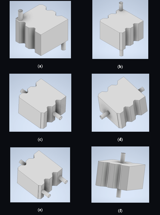
Fig. 2. Three-dimensional geometric models: (a) Variant 0, (b) Variant 1, (c) Variant 2, (d) Variant 3, (e) Variant 4, (f) Variant 5.
E. Mathematical Modelling and Governing Equations
1) Hydrodynamic Governing Equations

Under steady-state, incompressible, isothermal conditions, the RANS-averaged continuity and momentum equations are [2]:
where ρ is coolant density (kg/m³), v the Reynolds-averaged velocity vector (m/s), p the modified static pressure (Pa), μ the molecular dynamic viscosity (Pa·s), and μt the turbulent eddy viscosity (Pa·s). The effective viscosity (μ + μt) accounts for combined viscous and turbulent momentum transport.
2) Turbulence Modelling: SST k-ω
The turbulent eddy viscosity μt is determined by coupled transport equations for turbulent kinetic energy k (m²/s²) and specific dissipation rate ω (s⁻¹) [5]:
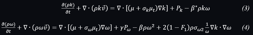
where Pk and Pω are production terms; β*, β, σk, σω, σω2 are SST closure coefficients; and γ is the production coefficient. The blending function F1 transitions between Wilcox k-ω (near-wall) and standard k-ε (free-stream), eliminating the free-stream sensitivity of the base k-ω model while retaining accuracy for adverse pressure gradient flows and incipient separation.
3) Physical Justification for Isothermal Analysis
Although complete thermal characterization requires conjugate heat transfer analysis, the local convective heat transfer coefficient h is fundamentally determined by the local velocity field through the Nusselt number correlation for staggered cylinder banks [1,2]:

where Red =

is the local diameter-based Reynolds number and C, m, n are geometry-dependent constants. As U → 0, Red → 0 and Nud → Nud,min (conductive limit), causing h to collapse dramatically. Isothermal stagnation zones are therefore direct spatial predictors of thermal hotspots. Systematic characterization and minimization of stagnation volume fraction across six configurations provides thermal optimization without the overhead of fully coupled conjugate equations, consistent with the frameworks of Almshahy et al. [5] and Shan et al. [2].
4) Hydrodynamic Evaluation Metrics
Three performance parameters quantify comparative hydrodynamic performance [1,5]. The hydraulic pressure drop Δp is the area-averaged static pressure difference between inlet and outlet:

The theoretical pumping power Ppump is the product of volumetric flow rate and pressure drop:

where V̇ = Ain·Uin. The stagnation zone volume fraction Vstag is a dimensionless metric for fluid regions where U < 0.02 m/s (5% of Uin):

This threshold-based indicator provides a configuration-independent, physically meaningful measure of hydrodynamically inactive regions, circumventing the qualitative ambiguity of streamline comparisons.
III. RESULTS AND DISCUSSION
A. Quantitative Hydrodynamic Performance Comparison
Under a uniform inlet velocity Uin = 0.4 m/s, maximum local velocity (Umax) and modified static pressure (pmax) were extracted across three orthogonal mid-planes: horizontal XY-plane (bisecting active cell height), horizontal XZ-plane (mid-height transverse cross-section), and vertical YZ-plane (longitudinal cross-section). Tables 2 and 3 present consolidated numerical outputs for all six configurations.
Table 2. Consolidated Maximum Velocity Magnitude Umax across Orthogonal Mid-Planes
| Configuration | Streamline Umax (m/s) | XY-Plane Umax (m/s) | XZ-Plane Umax (m/s) | YZ-Plane Umax (m/s) |
| Variant 0 (Diagonal Z-Flow) | 0.57 | 0.16 | 0.21 | 0.069 |
| Variant 1 (Inverted Diagonal) | 0.72 | 0.61 | 0.53 | 0.52 |
| Variant 2 (Front-Entry CIF) | 4.2 | 0.52 | 8.5 | 4.3 |
| Variant 3 (Side-to-Side Sweep) | 0.54 | 0.54 | 0.54 | 0.091 |
| Variant 4 (Dual-Inlet Converging) | 1.2 | 0.32 | 1.2 | 1.2 |
| Variant 5 (Vertical Bottom-to-Top) | 0.55 | 0.54 | 0.24 | 0.47 |
Table 3. Consolidated Maximum Static Pressure pmax across Orthogonal Mid-Planes
| Configuration | XY-Plane pmax (Pa) | XZ-Plane pmax (Pa) | YZ-Plane pmax (Pa) |
| Variant 0 (Diagonal Z-Flow) | 0.17 | 0.17 | 0.17 |
| Variant 1 (Inverted Diagonal) | 0.33 | 0.33 | 0.43 |
| Variant 2 (Front-Entry CIF) | 11 | 11 | 14 |
| Variant 3 (Side-to-Side Sweep) | 0.28 | 0.28 | 0.16 |
| Variant 4 (Dual-Inlet Converging) | 0.81 | 0.96 | 0.81 |
| Variant 5 (Vertical Bottom-to-Top) | 0.30 | 0.16 | 0.30 |
The tabulated data reveals a pronounced sensitivity of internal flow to port geometry, spanning more than two orders of magnitude in both maximum velocity (0.069 m/s for Variant 0 on YZ-plane to 8.5 m/s for Variant 2 on XZ-plane) and static pressure (0.16 Pa to 14 Pa). These results confirm that hydraulic resistance and flow uniformity are not independent objectives; they must be simultaneously optimized through judicious port topology selection.
B. Detailed Hydrodynamic Characterization
1) Variant 0: Baseline Diagonal Z-Flow
The baseline configuration channels coolant diagonally from the top-right upper corner to the bottom-left lower corner. At the inlet, the abrupt geometry transition induces a vena contracta, generating a maximum streamline velocity of 0.57 m/s confined to the diagonal corridor. On the XZ mid-plane, peak velocity is limited to 0.21 m/s; the XY mid-plane records 0.16 m/s. Most critically, the YZ mid-plane exhibits only 0.069 m/s—approximately 17% of Uin—confirming that bulk coolant bypasses the inter-cell volume along the high-momentum diagonal shortcut. Extensive quasi-stagnant zones (U ≈ 0 m/s) develop in the un-plumbed corners, causing h to approach its conductive lower bound. Although the uniform pressure drop of 0.17 Pa across all planes is the lowest of all configurations, the severe stagnation extent renders Variant 0 thermally inadequate for practical BTMS deployment. Fig. 3 shows the corresponding hydrodynamic field predictions.
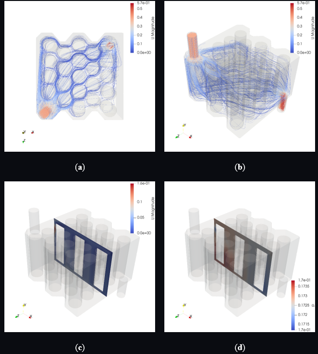
Fig. 3. Variant 0: (a) top-down streamline projection, (b) 3D isometric streamline tracer, (c) XY mid-plane velocity contour, (d) XY mid-plane static pressure distribution.
2) Variant 1: Inverted Diagonal Flow
Inverting the diagonal flow direction yields a 26% increase in peak streamline velocity (0.72 m/s) and, more significantly, near-parity across all three orthogonal planes: XY 0.61 m/s, XZ 0.53 m/s, YZ 0.52 m/s. This cross-plane uniformity—in contrast to Variant 0’s order-of-magnitude disparity—indicates substantially improved three-dimensional momentum penetration into inter-cell gaps, reducing stagnation zone extent. The associated maximum static pressure increases moderately to 0.43 Pa (YZ-plane), indicating greater hydraulic head dissipation through viscous shear work in the inter-cell passages—a trade-off thermally justified by the reduced stagnation volume fraction. Fig. 4 presents the corresponding flow field.
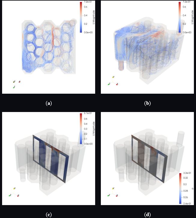
Fig. 4. Variant 1: (a) top-down streamline projection, (b) 3D isometric streamline tracer, (c) XY mid-plane velocity contour, (d) XY mid-plane static pressure distribution.
3) Variant 2: Front-Entry CIF
Aligning the flow perpendicular to the staggered cell array across the minimum hydraulic free area induces severe geometric throttling, analogous to a hydraulic orifice. The XZ mid-plane records 8.5 m/s—a 21-fold increase over Uin, consistent with vena contracta formation downstream of the central cylinder column. The YZ mid-plane reaches 4.3 m/s; streamline peak is 4.2 m/s. High local Reynolds numbers in the central corridor would maximize h locally, but the XY mid-plane is bounded at 0.52 m/s, confirming that elevated momentum is strictly confined to the central trajectory. The strong streamwise pressure gradient suppresses transverse diffusion, leaving extensive lateral stagnation zones in the peripheral wings—thermally analogous to Variant 0 deficiencies. The hydraulic penalty is severe: YZ-plane Δp = 14 Pa, approximately two orders of magnitude above Variant 0, yielding prohibitive pumping power. Variant 2 is unsuitable for module-wide temperature uniformity. Fig. 5 illustrates these flow characteristics.
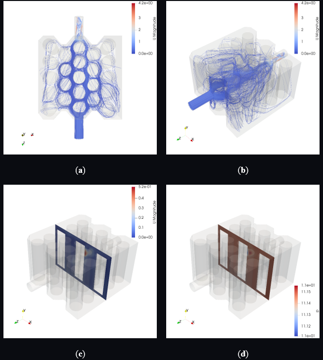
Fig. 5. Variant 2: (a) top-down streamline projection, (b) 3D isometric streamline tracer, (c) XY mid-plane velocity contour, (d) XY mid-plane static pressure distribution.
4) Variant 3: Longitudinal Side-to-Side Sweep
Directing coolant parallel to the longitudinal axis across the full width of the cell array yields the most spatially homogeneous in-plane velocity field. XY and XZ mid-plane peak velocities both stabilize at 0.54 m/s—near-perfect parity confirming a uniform two-dimensional horizontal flow structure without preferential bypass corridors. The YZ mid-plane peak of 0.091 m/s indicates limited vertical transport, implying marginally reduced convective refreshment at cell top and bottom extremities; however, streamline visualizations confirm excellent lateral distribution across all inter-cell gaps. Maximum static pressure is 0.28 Pa (XY, XZ) and 0.16 Pa (YZ)—comparable to Variant 0 but with demonstrably superior flow uniformity. Variant 3 is the superior choice for pumping-power-constrained BTMS applications. Fig. 6 illustrates these field results.
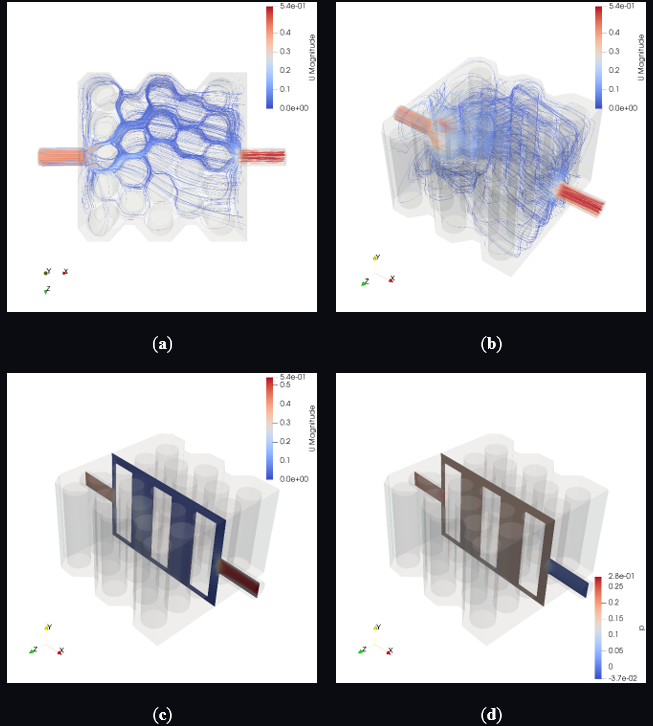
Fig. 6. Variant 3: (a) top-down streamline projection, (b) 3D isometric streamline tracer, (c) XY mid-plane velocity contour, (d) XY mid-plane static pressure distribution.
5) Variant 4: Dual-Inlet Converging
Symmetric dual-inlet impingement jets (peak 1.2 m/s, XZ and YZ) address the peripheral corner stagnation of single-inlet diagonal configurations by sweeping lower-left and lower-right casing corners. However, as the opposing jets encounter the first staggered cylinder row, momentum deflects laterally along the path of least resistance rather than penetrating the lower-central inter-cell gaps. This creates a residual low-velocity core stagnation zone: XY mid-plane peak is only 0.32 m/s, significantly below the jet maximum. Dual-inlet impingement thus partially redistributes rather than eliminates stagnation. Moderate hydraulic resistance yields static pressures of 0.81–0.96 Pa. Fig. 7 presents the Variant 4 flow field.
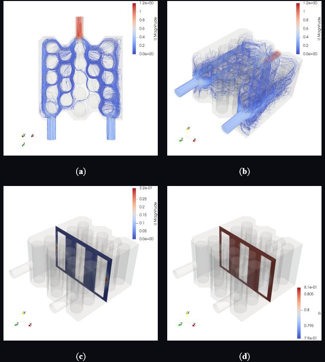
Fig. 7. Variant 4: (a) top-down streamline projection, (b) 3D isometric streamline tracer, (c) XY mid-plane velocity contour, (d) XY mid-plane static pressure distribution.
6) Variant 5: Vertical Central Bottom-to-Top Flow
A geometrically symmetric, buoyancy-aligned vertical configuration with centroidal inlet and outlet ports eliminates inherent preferential flow directionality. The maximum streamline velocity of 0.55 m/s is concentrated at the vertical core, with near-identical XY mid-plane peak of 0.54 m/s and YZ mid-plane peak of 0.47 m/s—demonstrating strong vertical momentum retention throughout the module height.
The XZ mid-plane velocity of 0.24 m/s captures radial expansion of the ascending central jet through inter-cell gaps, confirming effective peripheral coolant penetration without throttling or vena contracta effects. This radial spreading—driven by the transverse pressure gradient between the central high-pressure jet and peripheral low-pressure regions—ensures peripheral cell row refreshment absent dedicated peripheral inlets. Variant 5 simultaneously suppresses corner stagnation and distributes inter-cell gap velocities uniformly, without the core stagnation of Variant 4 or the peripheral bypass of Variant 0.
Maximum static pressure is 0.30 Pa (XY, YZ) and 0.16 Pa (XZ)—ultra-low and comparable to the most hydraulically efficient configurations—achieved without compromising three-dimensional coverage. Variant 5 most successfully balances hydrodynamic uniformity against pumping power economy. Fig. 8 presents the corresponding flow predictions.
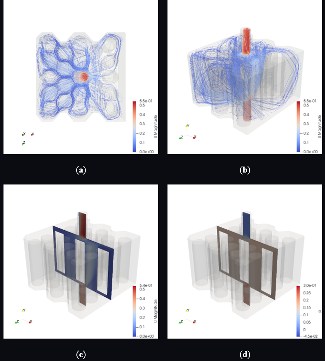
Fig. 8. Variant 5: (a) top-down streamline projection, (b) 3D isometric streamline tracer, (c) XY mid-plane velocity contour, (d) XY mid-plane static pressure distribution.
IV. CONCLUSIONS
A comprehensive three-dimensional isothermal CFD investigation has evaluated six inlet-outlet port topologies for a 23-cell 18650 LIB immersion cooling module in deionized water. By decoupling the hydrodynamic problem—leveraging the direct proportionality between local velocity, Reynolds number, and h—the study establishes a physically interpretable BTMS port optimization framework. Key conclusions are as follows.
Variant 0 (Baseline Diagonal Z-Flow) exhibits the most severely compromised uniformity: preferential diagonal channeling produces extensive quasi-stagnant peripheral zones (YZ-plane peak 0.069 m/s, ~17% of Uin) despite the lowest pressure drop (0.17 Pa). Thermally untenable stagnation renders this topology unsuitable as a practical BTMS design.
Variant 1 (Inverted Diagonal) achieves near-uniform cross-plane peak velocities (XY 0.61 m/s, XZ 0.53 m/s, YZ 0.52 m/s), indicating substantially improved three-dimensional momentum penetration over Variant 0 at a moderate hydraulic cost of 0.43 Pa.
Variant 2 (Front-Entry CIF) is the most hydraulically aggressive configuration. Geometric throttling produces 8.5 m/s at the XZ-plane and a prohibitive 14 Pa pressure drop, forming extensive lateral stagnation zones. This topology is unsuitable for module-wide temperature uniformity applications.
Variant 3 (Longitudinal Side-to-Side Sweep) achieves the most spatially homogeneous in-plane distribution (XY and XZ both 0.54 m/s, Δp = 0.28 Pa) at low hydraulic cost, making it the preferred configuration for pumping-power-constrained BTMS designs despite limited vertical momentum transport (YZ 0.091 m/s).
Variant 4 (Dual-Inlet Converging) addresses peripheral corner stagnation through symmetric impingement (peak 1.2 m/s) but generates a residual low-velocity core stagnation zone (XY 0.32 m/s), representing an intermediate-performance topology.
Variant 5 (Vertical Central Bottom-to-Top Flow) emerges as the most balanced overall configuration, combining low hydraulic resistance (Δpmax = 0.30 Pa) with superior three-dimensional coverage via buoyancy-aligned vertical momentum and radial jet spreading. The near-unity XY/streamline peak velocity ratio (0.54/0.55 m/s) confirms structural flow symmetry. Variant 5 is the most promising candidate for thermally uniform, energy-efficient BTMS implementation. Collectively, these results confirm that effective immersive BTMS design requires alignment of flow momentum vectors with the three-dimensional inter-cell gap network rather than brute-force velocity augmentation. Future work will extend this isothermal analysis to fully coupled transient conjugate heat transfer simulations, directly correlating optimized velocity fields with cell temperature distributions, intra-module uniformity indices, and thermal runaway onset thresholds under representative EV discharge duty cycles.
REFERENCES
[1] N. Aydin, D. Gurses, and E. Beyazoglu, “Efficient immersion cooling of lithium-ion batteries: A CFD and MOGA-based optimization study,” Appl. Sci., vol. 15, no. 21, p. 11564, 2025.
[2] W. Shan, Q. He, Z. Cao, Z. Zhang, Z. Dai, L. Zheng, and X. Li, “Numerical study of multi-nozzle inlet structure optimization for immersion cooling systems of large-scale lithium-ion battery pack,” J. Energy Storage, vol. 153, p. 120872, 2026.
[3] L. Zhao, J. Wang, M. Zheng, and M. Chen, “Design and performance optimization of liquid immersion cooling system for prismatic lithium-ion battery modules,” Int. J. Heat Fluid Flow, vol. 118, p. 110181, 2026.
[4] X. Zuo, P. Peng, Y. Wang, W. Li, W. Wu, Y. Qiu, and F. Jiang, “Water-immersion cooling for lithium-ion battery thermal management: A systematic experimental and numerical study,” Batteries, vol. 11, no. 11, p. 416, 2025.
[5] A. Almshahy, Z. Khatir, K. J. Kubiak, and M. Al Qubeissi, “Framework for rapid design and optimisation of immersive battery cooling system,” Eng. Comput., vol. 41, pp. 4225–4243, 2025.
[6] T. D. Le, Y. M. Bang, N. H. Nguyen, and M. Y. Lee, “Artificial neural network-based optimization of an inlet perforated distributor plate for uniform coolant entry in 10 kWh 24S24P cylindrical battery module,” Symmetry, vol. 18, no. 1, p. 14, 2026.
[7] L. Martellucci, R. Capata, and M. De Marco, “Comparative review of cooling systems for lithium-ion battery modules with 21700 cylindrical cells,” Batteries, vol. 12, no. 4, p. 107, 2026.
[8] J. H. Park, T. D. Le, and M. Y. Lee, “Multi-objective optimization on enhanced heat transfer and pumping power of cooling plate-based indirect cooling system for 6S2P lithium-ion battery module,” Energies, vol. 19, no. 9, p. 2218, 2026.
[9] Y. Luo et al., “A battery thermal management system integrating immersion preheating and immersion cooling,” ACS Omega, vol. 9, pp. 43523–43533, 2024.
[10] J. W. Han, K. S. Garud, S. G. Hwang, and M. Y. Lee, “Experimental study on dielectric fluid immersion cooling for thermal management of lithium-ion battery,” Symmetry, vol. 14, no. 10, p. 2126, 2022.
[11] G. Satyanarayana, D. R. Sudhakar, V. M. Goud, J. Ramesh, and G. A. Pathanjali, “Experimental investigation and comparative analysis of immersion cooling of lithium-ion batteries using mineral and therminol oil,” Appl. Therm. Eng., vol. 225, p. 120187, 2023.
[12] L. Giammichele, V. D’Alessandro, M. Falone, and R. Ricci, “Experimental study of a direct immersion liquid cooling of a Li-ion battery for electric vehicles applications,” Int. J. Heat Technol., vol. 40, no. 1, pp. 1–8, 2022.
[13] E. Tosun, P. Ilinčić, S. Keyinci, A. C. Yakaryilmaz, and M. Ozcanli, “A review on air and liquid cooling strategies for lithium-ion batteries,” Appl. Sci., vol. 15, no. 23, p. 12617, 2025.
[14] O. M. Oyewola, E. T. Idowu, M. J. Labiran, M. C. Hatfield, and M. L. Drabo, “Air-outlet and step-number effects on a step-like plenum battery’s thermal management system,” Batteries, vol. 11, no. 3, p. 87, 2025.
[15] E. Jiaqiang et al., “Effects of the different air cooling strategies on cooling performance of a lithium-ion battery module with baffle,” Appl. Therm. Eng., vol. 144, pp. 231–241, 2018.
[16] H. Park, “A design of air flow configuration for cooling lithium ion battery in hybrid electric vehicles,” J. Power Sources, vol. 239, pp. 30–36, 2013.
[17] W. Chen, S. Hou, J. Shi, P. Han, B. Liu, B. Wu, and X. Lin, “Numerical analysis of novel air-based Li-ion battery thermal management,” Batteries, vol. 8, no. 9, p. 128, 2022.
[18] T. F. Yang, P. Y. Lin, C. Y. Lin, W. M. Yan, and S. Rashidi, “Study on thermal aspects of lithium-ion battery packs with phase change material and air cooling system,” Case Stud. Therm. Eng., vol. 53, p. 103809, 2024.
[19] X. Peng, X. Cui, X. Liao, and A. Garg, “A thermal investigation and optimization of an air-cooled lithium-ion battery pack,” Energies, vol. 13, no. 12, p. 2956, 2020.
[20] A. Celen, “Experimental investigation on single-phase immersion cooling of a lithium-ion pouch-type battery under various operating conditions,” Appl. Sci., vol. 13, no. 5, p. 2775, 2023.
[21] M. Al Qubeissi, M. Al-Damook, A. Almshahy, and Z. Khatir, “Comparative analysis and design optimization of hydrogen-based battery thermal management,” Int. J. Sustain. Eng., vol. 19, no. 1, p. 2643025, 2026.