
1. Geometry and Setup
- Building Geometry
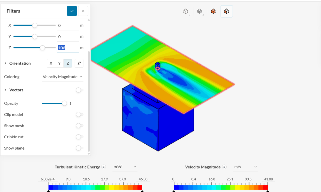
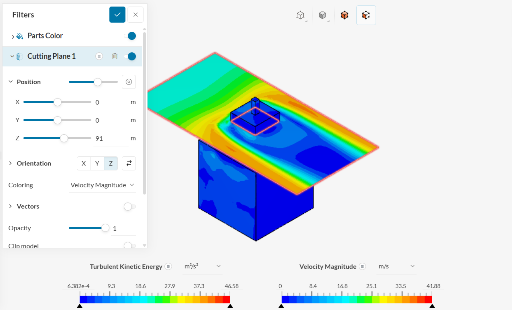
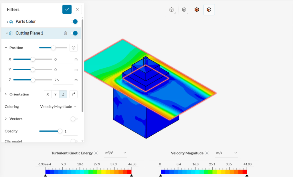
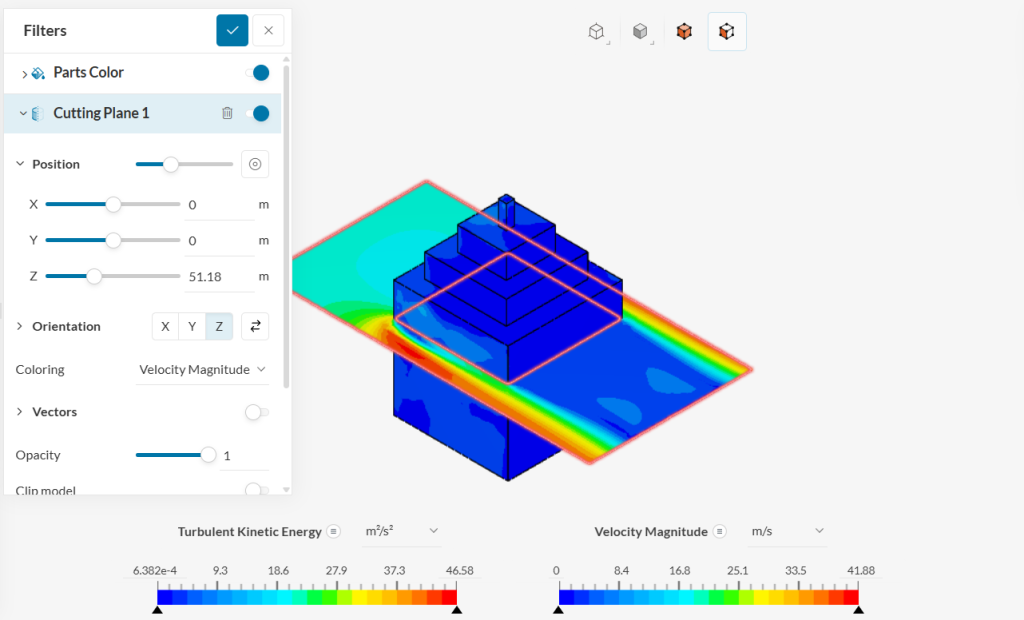
The model consists of a large cubic base with multiple stepped tiers on top. Each tier introduces additional edges and corners, which can influence local flow acceleration and the formation of vortices. - Cutting Plane Visualization
A horizontal cutting plane is shown at different elevations (approximately 100 m, 91 m, 76 m, and 51 m in the images). This approach highlights the velocity distribution at various heights above the building. - Color Contours
The color gradients (blue through red) represent velocity magnitude (m/s). Regions with higher velocity are typically shown in warmer colors (yellow to red), while lower velocities appear in cooler colors (blue to green).
2. Flow Features
- Acceleration Around Corners and Roof
- As the wind encounters the building’s windward face, it is redirected upward and around the corners.
- The highest velocities typically occur at sharp edges and over the roofline, where flow is forced to accelerate around obstacles.
- Wake Region and Recirculation
- A region of lower velocity (often green or blue on the velocity scale) forms downstream, indicating a wake or recirculation zone.
- Turbulence levels (visible in separate TKE plots, if available) increase in these wake regions due to flow separation.
- Effect of Stepped Tiers
- Each step on the building adds another location where flow can separate and reattach.
- These tiers can break up one large vortex into multiple smaller eddies, potentially influencing local aerodynamic loads on each tier.
3. Force Analysis
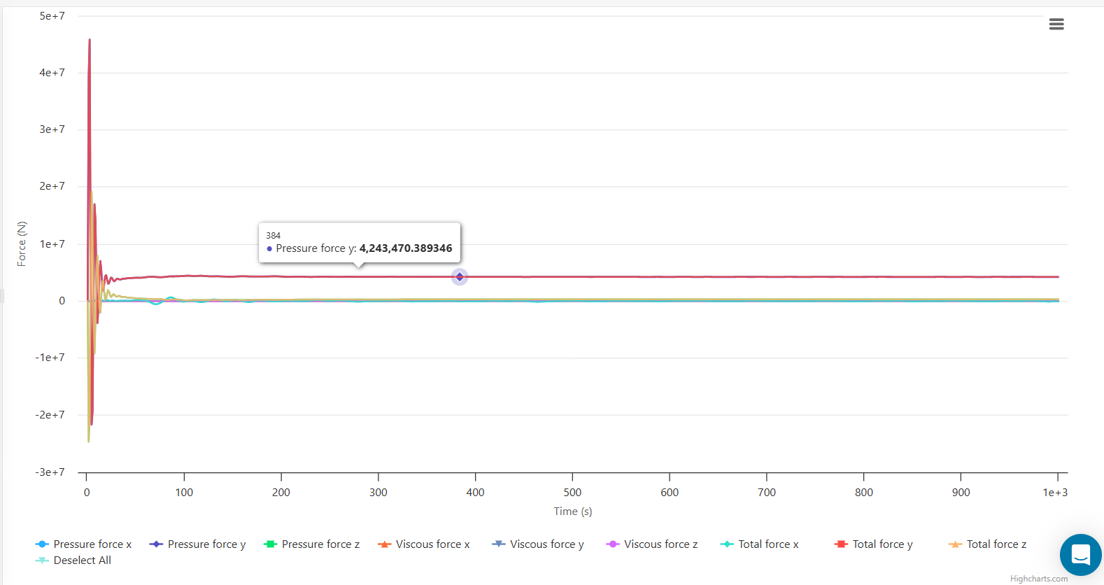
- Force vs. Time Plot
The chart indicates how pressure force, viscous force, and total force evolve over the simulation time. A few notable points include:- Dominance of Pressure Force: For bluff bodies such as buildings, the pressure component (form drag) tends to exceed the viscous component.
- Convergence to Steady State or Periodic Flow: The pressure force line appears to stabilize around a certain value (≈4.243×10⁷\approx 4.243 \times 10^7≈4.243×10⁷ N in the example shown), suggesting the flow field reaches a steady or quasi-steady condition.
- Total Force Magnitude: The total force is the sum of pressure and viscous forces. For a large structure exposed to a strong wind, forces in the order of millions of newtons are reasonable.
4. Key Observations and Design Implications
- Windward Face Loading
- The building’s front face experiences the highest positive pressure, making it a critical zone for structural design and façade attachment.
- Leeward and Side Suction
- The flow separates at the edges and creates negative pressure (suction) on the leeward face and sides. Although this pressure is typically lower than on the windward side, the large surface areas still contribute significantly to overall loads.
- Turbulence and Vortices
- Sharp edges and corners on each tier promote localized turbulence and vortex formation.
- Multiple tiers may reduce one large vortex into several smaller ones, altering the distribution of aerodynamic stresses.
- Practical Considerations
- Structural Integrity: Regions of high pressure and suction should receive additional reinforcement.
- Cladding and Roofing: Edges and corners exposed to strong flow require secure cladding systems.
- Occupant Comfort and Pedestrian Wind Environment: Elevated wind speeds near ground level or terraces might need mitigation strategies, such as windbreaks or landscaping.
Conclusion
The wind simulation around the stepped building model illustrates typical flow phenomena associated with bluff bodies, including flow acceleration at edges, wake formation, and the dominance of pressure forces. The force plot shows convergence toward a steady loading scenario, with pressure-based drag comprising the bulk of total aerodynamic load. Such analyses provide critical insight for structural design, cladding attachment strategies, and occupant comfort measures.